

meta data for this page
Thermocouple chain
Principle
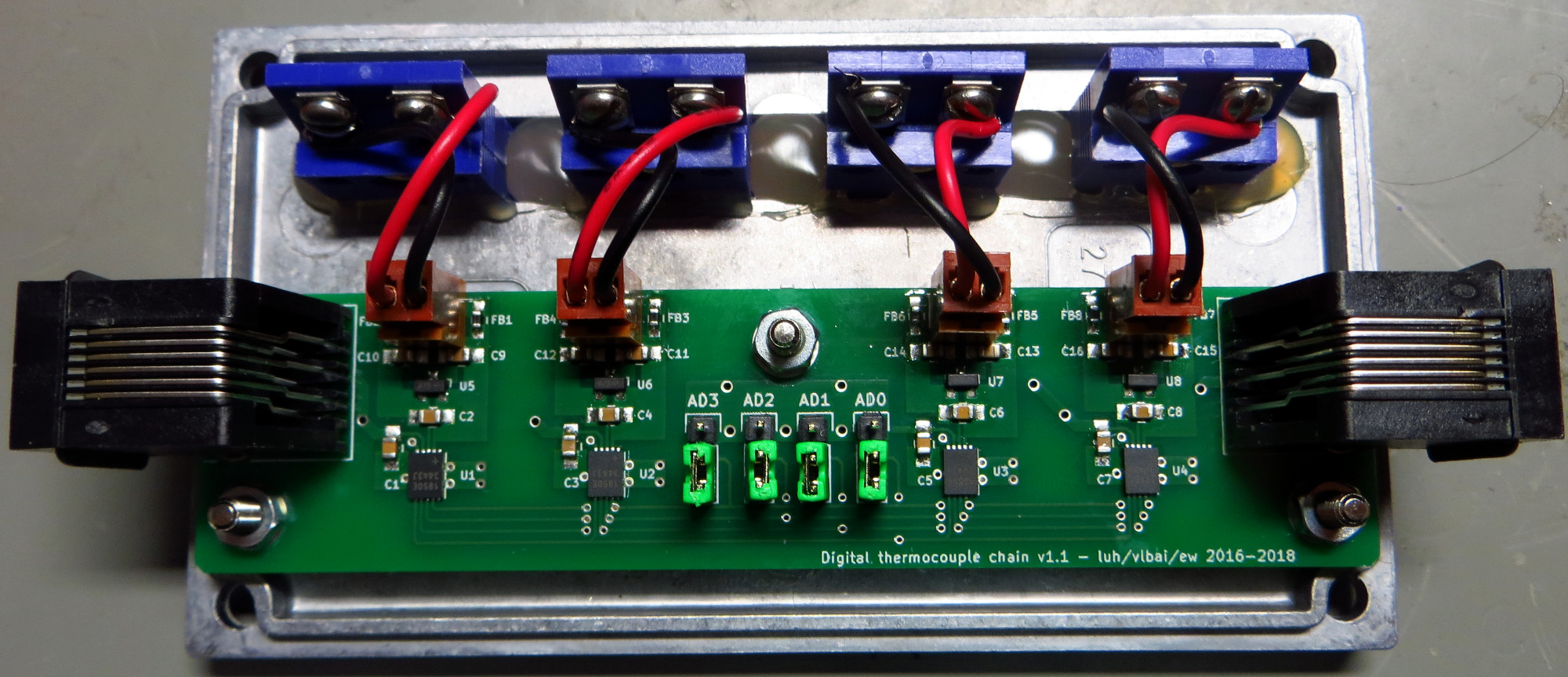
This project provides four thermocouple to digital channels. The boards can be chained on a one-wire bus to form a long chain of thermocouple inputs. Chain with more than 20 input channels (five boards) have been shown to work, only limited by the conversion time. The chain is compatible with any other one-wire slaves, for example DS18B20 temperature sensors (see the thermometer chain).
Chaining between boards is provided by RJ12/25 patch cables that are available for low prices at common distributors (ISDN cable). Pinout of the 6P6C connectors is as follows:
1: GND
2: Reserved
3: +3V3
4: Reserved
5: DATA
6: Reserved
All the functionality is embedded in the Maxim MAX 31850 chips. Specific thermocouple calibration tables are chosen at assembly time by choosing the correct member of the MAX 31850 family (all major thermocouple types available).
Development
- Developper: Etienne Wodey, wodey@iqo.uni-hannover.de
- June 2016 - February 2018
- Status: several chains operated routinely
Design files
Note: the standard footprint size for two-poles components is 0805 (in). The footprints are nervertheless much larger than normal to allow easy hand soldering.
Box
Steffen Sauer (Mg) has designed a box (based on Hammond 27134PSLA) for the individual units.
The plugs can be purchased from OMEGA (Part No. MPJ-x-F, where x is the thermocouple type).
One-wire masters
Ways to get a one-wire master (not all tested):
- GPIO bitbang, in particular on a Raspberry Pi (with
w1-gpiodriver) - DS2482 I2C One-wire master
- there also exists USB to one-wire adapters
In all cases, make sure that the supply voltage is around +3V3. Also, please note that the boards do provide a separate power supply line. Parasitic power is therfore not required.
Meckerliste
Was für die nächste Version zu tun ist: ( : verworfen,
  : in Arbeit,
  : im Schaltplan, aber noch nicht im Layout,
  : erledigt)