meta data for this page
FixedSine
Function
This generator provides a pure sine signal with very little drift and phase noise. It sacrifices flexibility for stability, compactness and simplicity.
Options and Alternatives
The generator can be used with any square wave oscillator from the series AQO 7050 by Auris. Refer to the Bürklin catalogue for a list of available frequencies.
The resistors and inductors of the filter have to be adapted to the specific operation frequency. Refer to table 1 for values known to work. The filter design tool hosted at the university of York, UK is recommended to determine reasonable values from scratch.
| Freq. | R3 | L3 | C14 | L4 | C16 | R4 | type |
|---|---|---|---|---|---|---|---|
| 16.9 MHz | 50 Ω | 1.5μH | 150 pF | 2.2 μH | 100 pF | 300 Ω | chebychev |
Performance
A generator configured for 20.00 MHz was characterized:
- frequency drift integrated over a few minutes is less than $1\times 10^{-8}$.
- frequency drift integrated over approximately one second is less than $1\times 10^{-9}$.
- according to the manufacturer the jitter of the oscillator is below 1 ps.
Timeline
- The project was started in July 2015
- The first prototype was operational in August 2015
Status
About ten devices are in use at Mg.
Developer
Nandan Jha
User
Mg
Principle of Operation
An integrated quartz oscillator provides a stable square wave signal. A passive four pole LC filter removes the higher harmonics to render a near perfect sine waveform. An amplifier is used on output to increase the amplitude and the ability to drive low impedance loads.
Schematic
- The schematic im PDF-Format
- The source of the schematic can be found on the download page of the wiki.
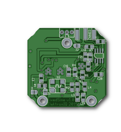
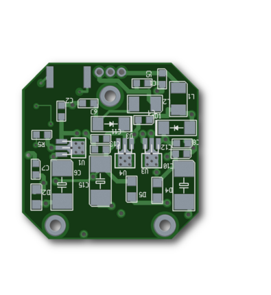
Layout
- Size of the PCB: 40.5 x 40.5 mm
- Supply: JAE IL-G, 3Pin, +15 V, GND, -15 V
- Input: none
- Output: SMA
- Displays: none
- PDF of the layout: fixedsine_layout_v1.1.pdfDer Bestückungsdruck
- Bill of materials: fixedsine_v1.1_koll.pdf, fixedsine_v1.1_koll.xls
- A zip of the gerber files for pcb production
- The source of the layout in geda format is available at the download page of the wiki.
Enclosing
Mounting holes of the generator and connectors are compatible with the design of the photodiode amplifier PD-ac-dc.
Test
The oscillator should oscillate right out of the box.
Images
Cost
| item | amount | value | total | remarks |
|---|---|---|---|---|
| 4-layer PCB | 1x | 24.50 € | € | 1/4 of 95.43 EUR (Basista-Prototyping) |
| enclosing | 1x | 8.20 € | € | Hammond 1590LLBBK |
| SMA connector | 1x | 1.60 € | € | |
| JAE IL-G connector, 3 pin | 1x | 0.30 € | € | |
| voltage regulator | 2x | 0.20 € | € | SOT89 |
| 100 µH inductor | 2x | 0.30 € | € | |
| 10 µF tantalum cap | 3x | 0.80 € | € | |
| HF inductor | 2x | 0.50 € | € | Epcos B82498F |
| oscillator | 1x | 2.30 € | € | Auris AQO-7050 |
| opamp AD817 | 1x | 6.55 € | € | fast, high slew rate |
| resistors, caps, diodes | 25x | 0.02 € | € | all parts sized 0805 |
| off-cuts | 5.00 € | |||
| total overall: | € | |||
When produced as a mini series of 60, the price for the PCB drops to 5.20 € per piece.
Todo
(Icons: 


- Add a 1 nF capacitor in parallel to R5. This helps get rid of offset voltages (WTF?)
- Use AD817 op-amp due to its fast slew rate. C19 and C21 are not needed for this op-amp.
- Opamps aree borderline fast enough
Better use MMICs in the next version. E.g. ERA-8, or similar.
- A polygon on top is not connected to ground.
- Ground should be done more properly
- Diode D3 is drawn in the wrong direction in the layout

