meta data for this page
CurrentStabilisation
Funktion
One device, multiple tasks:
- Power Supply for LEM ULTRASTAB via D-Sub
- Read current & transduce to Voltage with high precision option
- Set current via analog input
- switch current on/off via MOSFET control
- PID feedback to (high current) power supply including sample and hold option
- PID feedback to MOSFET to control / switch current with output offset
- interlock (ULTRASTAB status, external)
Optionen und Alternativen
- There is a footprint for ultra high precision current sensing resistor.
- instead of ULTRASTAB D-Sub, a BNC can be connected to current input
- via population you can select whether to measure current or voltage (no shunt resistor). Then it should be usable as dual PID.
- PSU output limit (0-10V) can easily be disabled
Performance

Date
Begin of Project: Oktober 2016
Status
- schematic and pcb layout done on KiCad
- version v1a ordered at Basista on 2016-11-01, 3 pc for prototyping
Aufwand für Nachbau: 
Entwickler
Christian Meiners, meiners@iqo.uni-hannover.de
Main Ideas based on prototypes an schematics from Klaus Zipfel.
Anwender
VLBAI Magnesium
Schaltungsprinzip
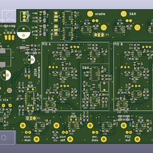
current from LEM ultrastab is transduced to voltage using a shunt and a diffamp. A error signal is generated by adding a iverted set signal. This error signal is fed into two PIDs. PID A has A Sample and hold option which works as follows: the PID output is fed into the S&H circuit, once activated the S&H outputs a constant voltage which was previously the PID output signal. At the same time the difference between this constant voltage and the actual PID output voltage is fed as a new error signal to the PID input.
- The S&H feature can be enabled / disabled via TTL. If disabled the output returns to zero on disable.
- PID B returns to zero on disable using the same mechanism but without the S&H feature.
- all digital inputs are optocoupled
- all analog inputs are differential
- the MOSFET out can drive high capacity
- the PSU output is limited to 0-10V
Schematic
- All files can be found on http://bibo/git/CurrentStabilisation.git
- Schaltplan in PDF-Format
- Die Source des Schaltplans ist auf der Download-Seite des Wiki abgelegt.
Layout
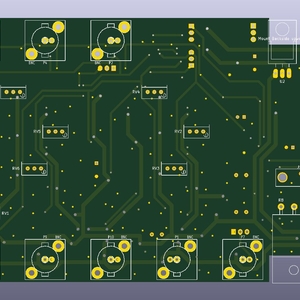
- PCB size: 160 x 100 mm
- Supply: > +/-15V
- Inputs:
- Ultrastab (D-Sub) or Current/Voltage (BNC)
- control voltage to set the current,
- TTL enable
- TTL enable S&H
- TTL interlock
- Outputs:
- current monitor
- error monitor
- PSU control
- MOSFET control
- Displays: none
- Die Bestückungsliste:
- Die gezippten Gerberdaten für die Bestellung der Platine
- Die Source des Layouts im pcb-Format liegt auf der Download-Seite des Wiki.
Housing
In progress, Hammond for 160*100 mm, Height?

Test
Up to now only PID A is populated (exept D) after Hacking the logic at the S&H IC, it works as expected. after switching in hold mode, the current seems to be a bit lower than the initial setpoint. this might be caused by the big hold capacitor. Maybe after 0.5 sec. it is not entirely loaded. The hold time seems to be huge, after 30s there is almost no change visible, seems to be a fraction of a Millivolt. So it might be an option to change the Cap to a smaller one, leading to a smaller hold time, but a more precise hold value.
The idea of having the current on for a longer time before switching to hold mode didn't really help, so it doesn't seem to be an problem related to the loading curve of the hold cap. after a hold time of ~4 minutes, the current monitor voltage dropped from ~39.6 mV to 39 mV.

Usage
Input Signals
| Input | Type | Description |
|---|---|---|
| ULTRASTAB (D-SUB) | analog current (differential) | current input from current transducer, can be modified to differential voltage input. |
| Current set | analog voltage (differential) | current setpoint |
| enable | digital voltage (optocoupled) | high: PIDs enabled, outputs active low: disabled, MOSFET out turned to zero. |
| S&H | digital voltage (optocoupled) | high: S&H active, PID A holds voltage on disable low: S&H diasbled, PID A returns to zero on disable |
| interlock | digital voltage (optocoupled) | high: device operational, low: all outputs off, PIDs return to zero |
Jumper Settings
| Jumper # | Feature | options |
|---|---|---|
| 1 | Current monitor output reference | pin 1 (right): normal gnd pin 3 (left): clean gnd |
| 2 | MOSFET output selection | pin 1 (right): PID B (without S&H) pin 3 (left): PID A (with S&H) |
| 3 | Enable Input usage | pin 1 (left): connect enable in pin 3 (right): connect to gnd, permanent enable |
| 4 | ULTRASTAB interlock usage | pin 1 (top): ULTRASTAB interlock used pin 3 (bottom): ULTRASTAB interlock ignored |
| 5 | External Interlock usage | pin 1 ( left): ext. interlock used pin 3 (right): ext. interlock ignored |
| 6 | Sample and Hold usage | pin 1 (bottom): S&H input connected pin 3 (top): S&H permanently enabled No Jumper: S&H permanently disabled |

Bilder
Kalkulation

| was | wieviel | E-Preis | Preis | Anmerkung |
|---|---|---|---|---|
| Leiterplatte | 1x | ??.?? € | € | 1/n von XXX EUR |
| Gehäuse | 1x | ??.?? € | € | |
| * | ?x | ??.?? € | € | … |
| R,C | ??x | 0.02 € | € | Bauform 0805 |
| Bestückung | ??.00 € | bei SRM | ||
| Verschnitt | ?.?? € | |||
| Summe | € | |||
Meckerliste
Was für die nächste Version zu tun ist: (


Logic at S&H is wrong. On prototypes (v1a) it can be hacked (pins 10 & 11 have to be interchanged).
add values for Zener diodes
add diodes across voltage regulators to protect them
5V regulator is TS78L05ACY pinout (out - gnd - in)
change Mosfet ouput stage to twice noninverting. negative offset added on the nagative input of frist OpAmp, such that the MOSFET pulldown works
add footprints for IC shields for instr. Amps and sum
larger cutout for XLR Power input
- increase through hole sizes (hard to unsolder)
supply capacitors laying on rear side
interlock status leds
add second ref footprint parallel in current set path for more gain flexibility

